The Nexalus Thermal Management Solution
Nexalus Direct Cooling CPU Thermal Management Solution
The full cooling solution for data centre servers
The implementation of water-cooling in electronics thermal management creates new engineering challenges that are significantly different to those associated with air-cooling (Learn more here).
The Nexalus data centre CPU thermal management technologies are highly integrated cooling systems that have been engineered to tackle the two key technical challenges that arise when implementing water cooling;
- The water-cooled heat sink must provide aggressive cooling to the extent that its effective thermal resistance becomes a minor portion of the overall thermal budget of the full core-to-coolant system. This must be achieved at moderate to low volumetric flow rates and pressure drops.
- The TIM2 material and associated mounting system must combine to create as low as possible thermal resistance across the IHS-to-Heat Sink thermal joint.
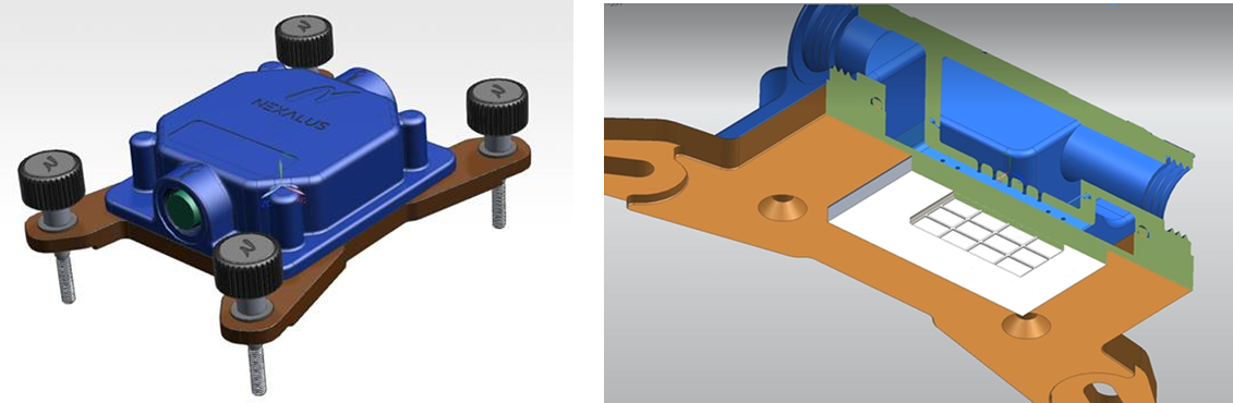 Fig L2.1
In order to illustrate the Nexalus technology, Figure L2.1 depicts the Nexalus S1 water cooling system for the Intel i9 7980XE. The cooling architecture is comprised of two separate yet interdependent sub-systems; the liquid-cooled direct attach waterblock and the TIM2 thermal paste and mounting system.
The Waterblock: The Nexalus waterblock is a 1U compatible two-part fully integrated thermal-hydraulic system comprised of an upper precision injection moulded plastic water manifold cum flow delivery system mechanically sealed to a lower copper base plate. The injection moulded plastic component facilitates design freedom not afforded by competing manufacturing processes. This has been leveraged here in the engineering of an extreme performance impinging jet array forced convection heat transfer cooling technology. Pumped water enters an upper plenum which is forced through a nozzle orifice plate. The water issues from the individual jets at very high velocity and impinge onto the heated copper base, creating very high convective heat transfer coefficients. Thus, a key differentiator of the Nexalus water-cooling technology is the innovative engineering of the flow hydrodynamics on the delivery-side to the system. This creates extreme cooling effectiveness without having to resort to machined micro-features on the copper baseplate to achieve the high rates of heat transfer. Furthermore, by carefully controlling the size and spacing of the jets in the array, tailored cooling for different CPUs have been engineered with exceptionally high convective heat transfer coefficients and moderate overall volumetric flow rates and pressure drops.
TIM2 & TIM2 Mounting Assembly: The Nexalus TIM is engineered to strike the balance between having (i) high bulk thermal conductivity, (ii) carefully tuned fluid properties to ensure a low bondline thickness at moderate assembly pressures, and (iii) ideal wetting properties to mitigate contact resistance at the metal-TIM interface. Combined, these create an exceptionally low thermal impedance across the TIM2 thermal joint between the CPU IHS and the Nexalus waterblock baseplate.
The TIM2 material properties are not the only factors that ensure a low resistance thermal joint. Assembly factors such as too much or too little applied force on the TIM and/or uneven mechanical loading can severely compromise performance. To overcome these assembly pitfalls, Nexalus has engineered an innovative toolless mounting system using proprietary Nexalus torque screws, as depicted in Figure L2.1. The Nexalus torque screws are designed to be hand-turned in sequence to provide even mechanical loading on the TIM. Each screw then disengages at a set torque that is specifically set for the given Nexalus Waterblock-Nexalus TIM-CPU combination. The result is an engineered solution for toolless TIM assembly that creates precision mechanical loading to ensure the minimum possible thermal resistance simply and repeatedly.
The Test: This illustrative test was performed on the OCP Winterfell server. This server incorporates two Intel Xeon E5 2678 V3 CPUs onto which two Nexalus S1 waterblocks were mechanically fastened using with the Nexalus Precision Torque screws subsequent to the application or Nexalus TIM. Water at a nominal temperature of 24oC was circulated to the waterblocks which themselves were plumbed hydraulically in parallel. The flowrate was controlled via a valve. CentOS Linux 8 was used to control the CPU loading and monitor the CPU temperatures.
The Results: The results are depicted in Figure L2.2 in terms of the average of the two CPUs. The expected trend of increased CPU temperature with increased percentage load is observed, with a steep increase from idle power (~5%) though tends to plateau when approaching 100% load, which represents approximately 100 W of thermal power from each CPU i.e. ~200 W total thermal power temperature of the two units; about half of the total power to the server. The key observation here is that at full load and a mere 0.4 L/min, the CPU temperature is only 57oC, which is over 25oC below the allowable operating temperature 84.5°C. Halving the flow rate increases the operating temperature to 66oC, still well below the maximum allowable temperature.
 Fig L2.2
The Nexalus Thermal Management Components
Nexalus Water Cooling Solution
Engineered Heat Sink for High Performance Cooling
L2A: The Nexalus S1 Water-Cooled Heat Sink
Design for Thermal Hydraulics
The Nexalus S1 water-cooled heat exchanger is engineered for direct-attach cooling of server CPUs. With a height of only XX mm above the CPU mounting plane, it is designed to be compact and easily fit in 1U server architectures with room to spare.
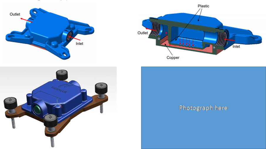 Fig L2A.1
The thermal-hydraulics of the Nexalus S1 is engineered to implement highly effective jet array impingement heat transfer. Jet array impingement heat transfer involves the forcing of high velocity water jets from a patterned array of nozzles onto a heated metal base. (Learn more here: Jump out to L4JetA).
The high velocity of the jets create exceptionally high convective heat transfer coefficients on the target heated base. As importantly, the pressure drop is almost entirely associated with the contraction of the fluid into the nozzles, making it moderate in magnitude, straight forward to engineer and not dependent on the target heater size (Learn more here: Jump out to L4JetB).
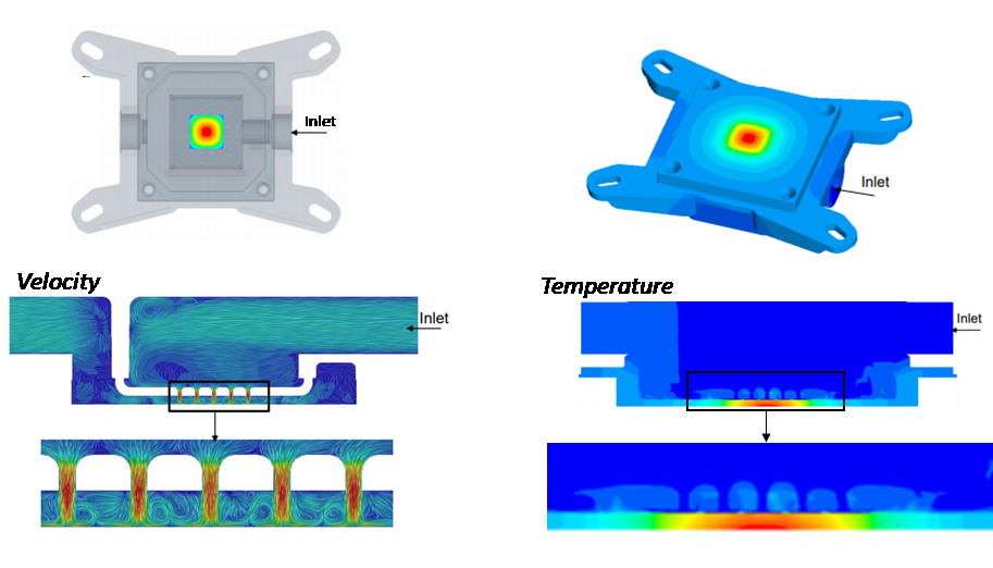
To give a sense of the capability of the Nexalus S1 jet array impingement cooling technology, an example is given here where a small (14.1 mm x 14.1 mm) heat source generating 500 W of thermal power on the Nexalus S1 base. This represents a heat flux of over 250 W/cm2, which is extreme and far beyond the capacity of any air-cooled technology. For illustration purposes, the goal here is to cool the point where the average source temperature is below 85oC with 20oC water. The CFD results, depicted in Figure L2A.2, have determined that a volumetric flow rate of only 2.5 L/min can generate an overall heat transfer coefficient of 40,000 W/m2K, which is sufficient to cool the 250 W/cm2 heat source to 84oC. This is achieved by creating water jets with a velocity of over 3 m/s, producing high convective heat transfer coefficients on the top surface of the heated base. This acts in conjunction with the heat spreading capability within the copper base, which acts to increase the surface area for convective cooling. Together, the high convective cooling effectiveness and the heat spreading within the copper base act to produce a source-to-sink thermal resistance of only 0.13 K/W, which is remarkably low for such a small heat source. Importantly, this extreme conjugate cooling is achieved with just over 5 kPa of pressure drop.
This illustrative example shows just how effective liquid jet array impingement thermal-hydraulics is when implemented to cool localized and high power heat sources, like those in modern CPUs. This extreme cooling performance along with several other technical and practical advantages has motivated Nexalus to depart from traditional waterblock-type heat sinks which, being based on microchannel technology, have in our engineering opinion reached practical performance and fabrication limits (Learn more here: Jump out to L4JetC).
When engineering a cooling solution for CPU thermal management, the waterblock must be mounted and mechanically pressed onto the Integrated Heat Spreader (IHS) with a layer of Thermal Interface Material (TIM). The IHS represents an additional thermal resistance in the overall package-waterblock stack, and combines with TIM1 and the semiconductor die to cumulate in the level 1 portion of the thermal stack. The level 2 portion of the stack is comprised of TIM2 and the waterblock. The thermal design must take into both the level 1 and level 2 resistances in the total stack, and these are coupled via the conjugate heat transfer (i.e. heat spreading) within the IHS and base of the waterblock (Learn more here: Jump out to L3B).
To provide a sense of the exceptional performance of the Nexalus S1 waterblock, an example is given here where it is used to cool one of the most powerful CPUs on the market; the 16 core Intel i9 7980XE.
 Fig L2A.3
The Test: This test used the Intel i9 7980XE on a Asus ROG Maximus XI Hero motherboard. The Nexalus S1 waterblock was mounted on the Intel i9 7980XE subsequent to application of the Nexalus TIM2 on the CPU IHS (Learn more here: Jump out to L2B). Optimum and even pressure on the TIM was ensured by use of the Nexalus Precision Torque Screws to mechanically fix the Nexalus S1 to the CPU (Learn more here: Jump out to L2C). Water was drawn form a constant temperature reservoir held at 20oC by a Liang?? D5 pump and plumbed to the Nexalus S1 such that it ran in an unobstructed open hydraulic loop. The CPU was overclocked to 4.9 GHz at 1.2435 V using the y-cruncher software and the core temperatures and powers monitored by the Core Temp software.
The Results: Under these overclocking settings, the Intel i9 7980XE produced a CPU power of 199 W. Under this thermal loading and the ment systems kept the average core temperature to 73oC with a standard deviation of 5.5oC across the 18 cores. To put this in perspective, the thermal design power (TDP) of the Intel i9 7980XE is 165W, and this is the power that an air cooling solution would incur a core temperature of below XXoC. The Nexalus server cooling solution is thus capable of cooling to far below the maximum operating temperature at XX times the thermal power.
A second example in now given for the 16 cores AMD Threadripper 3970X. This is a completely different CPU architecture compared with the Intel i9 7980XE in that the IHS is significantly larger since this CPU is a multichip module, incorporating 4 individual 4 core dies. This being the case, the Nexalus EPYC waterblock, albeit the same overarching thermal hydraulic architecture, is notably different in size and mounting configuration compared with the Nexalus S1.
Nexalus technology drivers
L3A: What are the Nexalus technology drivers?
When cooling processor units (CPU, GPUs etc.), the heat is generated by the cores and must be effectively transferred to the heat sink fluid in order to maintain the core temperatures within safe operating limits. In Figure 1, an example of an Intel i9 7980XE is depicted. The off-the-shelf CPU package incorporates the cores, the semiconductor die, Thermal Interface Material 1 (TIM1) and the Integrated Heat Spreader (IHS). The package itself represents a stack of materials and interfaces across which the heat generated by the cores must be transferred to the top of the externally cooled IHS. This is referred to as the 1st level of the thermal stack, since it represents the resistances to heat transfer within the off-the-shelf package and is thus fixed in terms of engineering design of a thermal management system.
On top of the IHS, a heat sink is mechanically attached. The function of the attached heat sink is to transfer the heat to a fluid medium, which is subsequently transported away from the system. This is referred to as the 2nd level of the thermal stack, since it is the region where electronic packaging engineers and/or thermal designers can engineer the appropriate cooling solution for a given off-the-shelf electronics package.
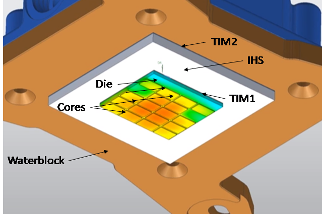 Fig L3.1
Whenever heat transfers through, across or into different mediums, there is an associated resistance to the heat flow. Ultimately, the resistance causes a drop in temperature, and the magnitude of this drop depends on (i) the amount of heat being transferred, and (ii) the magnitude of the resistance. In terms of the overall source-to-sink stack, the system is additive (thermally in series), in that each temperature drop within the stack adds with the next and the sum total represents the total temperature drop between the cores and the coolant;
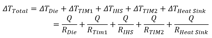
It is thus the job of the electronics packaging engineer and/or thermal designer to engineer the 2nd level thermal management system in such a way that the overall temperature drop is within safe margins for a given thermal design power (TDP). This ‘safe’ overall temperature drop is referred to as the allowable thermal budget. Clearly, for a given electronics package and TDP, the thermal engineering must focus on the thermal resistance associated with TIM2 and the attached heat sink, RTIM2 and RHeat Sink respectively.
L3B: How does it all stack up against air-cooling?
Straightforward mathematical tools exist to give a Stage 1 design approximation of the thermal resistances associated with a full thermal stack i.e. from the junction to the coolant [reference]. These mathematical models are useful for early design stage vetting of design options as they include all of the important physics, including the conjugate heat transfer associated with heat spreading in the IHS, without having to use more time and cost intensive simulations and/or experiments